Missile Systems
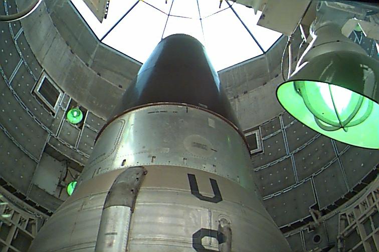
The LGM-25C ballistic missile (Titan IIc) consisted of a two-stage, liquid rocket-engine-powered vehicle and a reentry vehicle. The first stage, Stage I, is the booster, Stage II is the sustainer. The reentry vehicle is a Mark VI. Provisions were included for the inflight separation (staging) of Stage II from Stage I, and for the separation of the reentry vehicle from Stage II. Both Stage I and Stage II contained similar systems, such as propellant, pressurization, propulsion, hydraulic, and electrical. In addition, Stage II contained the flight control and inertial guidance systems. In this section we will describe the construction of the missile airframe and discuss the function and operation of each of the missile systems.
Since the missile airframe was the supporting structure for all missile systems, its specific construction characteristics should be presented first. This is followed by information about the R/V, propulsion system, pressurization system, hydraulic system, electrical system, missile guidance set, and flight control system.
Summary Stats
length: 103' / 31.3 m
diameter: 120" / 3.05 m
launch weight: 327,000 lb / 149,700 kg
end speed: 24,000 km/h
range: 6296 - 8100 nm / 4000 - 15000 km
ceiling: about 700 mi.
accuracy/CEP: 0.5-0.8 nm
Missile Airframe
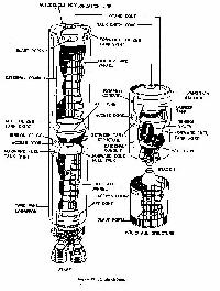 Fig. 12
The airframe was the principal structural portion of the missile. It was cylindrical and constructed of lightweight metals. Figure 12 shows in detail the construction features of the LGM25C airframe. Notice that each stage had fuel and oxidizer tanks arranged in tandem, with the walls of the tanks forming the skin of the missile. The oxidizer tanks were the largest and are above the fuel tanks. An external conduit was attached to the surface of the tanks to provide passage for tubing of small diameter and bundles of electrical wiring. Access doors were provided in the missile's forward, aft, and between-tank sections for inspection and maintenance. Access doors for tank entry are located on the forward domes of all tanks. The reentry vehicle is mounted on top of Stage II.
Stage 1
The major assemblies of the Stage I airframe are illustrated in figure 12. They consisted of a tail skirt (not shown), between-tanks structure (includes the forward fuel tank skirt and aft oxidizer tank skirt), oxidizer tank, the forward oxidizer tank skirt, and the interstage structure. The between-tanks structure, oxidizer tank, forward skirt, and interstage structure were all fabricated assemblies with riveted skin, stringers, and frames. The stringers and frames were structural members that give the airframe shape and strength. The oxidizer and fuel tanks were welded structures consisting of a forward dome, tank barrel, and aft dome or cone. Some statistics on the Stage I airframe are:
a. Length-70 feet.
b. Diameter-10 feet.
c. Approximate weight loaded-258,000 pounds.
d. Approximate fuel capacity-84,600 pounds.
e. Approximate oxidizer capacity-162,500 pounds.
The fuel tank aft skirt contained two airscoops mounted 180' apart. Air ducting was used within the skirt to direct the air. These scoops and ducts prevent hot gases and vapors from recirculating in the Stage I engine compartment.
The Stage I fuel tank consisted of the four skin panels and the four longeron panels. The remainder of the tanks were constructed with four skin panels. Baffles were placed at the outlet of each tank to prevent vortexing the propellants during operation. Vortexing is the whirling or circulating motion in a liquid mass which tends to form a cavity or vacuum in its center. A whirlpool and an eddy are examples of vortexing.
The oxidizer tank forward skirt in Stage I contained 20 blast ports of teardrop design located at the forward end of the skirt. During staging, these and the 16 exhaust ports in the interstage structure vented exhaust gases from Stage II engine firing. This is known as "fire in the hole separation." The interstage structure consisted of aluminum alloy panels riveted to an aluminum frame. There were 16 rectangular exhaust ports is groups of four per quadrant.
The interstage structure was approximately 122 inches long and was made of aluminum alloy panels riveted to an aluminum frame. The framework consisted of frames, stringers, and stiffeners. At the aft end, there were 16 rectangular exhaust ports located in groups of four per quadrant. Stage II was attached to the forward end of this structure by four staging bolts. The aft end was attached to the forward oxidizer tank skirt by bolts. The structure was considered part of Stage I but, during transportation, handling, installation, and removal, it remained attached to Stage II for ease of handling. During staging, the interstage structure remained with Stage 1.
Stage II
Figure 12 shows that the major assemblies of the Stage II airframe were the aft skirt, fuel tank, between-tanks structure, oxidizer tank, and the transition section. The aft skirt, between-tanks structure, and transition section were fabricated assemblies using rivited skin, stringers, and frames. The oxidizer and fuel tanks were welded structures with forward and aft domes. Some statistics on Stage II are:
a. Length-20 feet.
b. Diameter-10 feet.
c. Approximate weight loaded-64,000 pounds.
d. Approximate fuel capacity-20,700 pounds.
e. Approximate oxidizer capacity-37,200 pounds.
Stage II contained one engine, guidance equipment, translation and pitch rockets, and a means for attaching the reentry vehicle. The tanks were constructed so that the tank skin was the missile skin and forms the major portion of the stage. No external fasteners went through the walls of the tanks because of the danger of liquid leaks. Access doors were located on the forward, aft, and between-tanks sections for inspection and maintenance. There were two conduits for the entire missile-one for each stage. They were located on the outside of the propellant tanks, 60' counterclockwise from the target side of the missile. These conduits contained electrical wiring and pipes for the autogenous pressurization (self-generated) system.
Visual Inspection of the Airframe. Normally, the crew missile systems analyst technician (MSAT) inspected the missile airframe only when some other activity, such as troubleshooting or missile verification, had been done. During daily shift verification (DSV), the MSAT and missile facility technician (MFT) opened the access door on level 8 to check for such things as hydraulic oil leakage and water or corrosion in the flame deflector. Periodically, the MSAT and another crew member performed a walk-around visual inspection of the reentry vehicle.
Reentry Vehicle
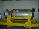 W53 Nuclear Warhead
The Mk. VI R/V was the most important item in the entire Titan II weapon system. All other missile devices operated to deliver the R/V to a specific point in space that will produce a freefall trajectory to the target. The R/V contained a W-53 nuclear warhead. Most of the specific data concerning the W-53 warhead were classified and cannot be included here. However, public documents have stated that the W-53 warhead had a nuclear yield of between 9 and 10 megatons.
 Mk. VI R/V
The R/V was mated to Stage II by the mating ring. The R/V was 14 feet long and weighed up to 8800 pounds. Its nose portion was covered with ablative material to protect the warhead from heat generated by reentry into the atmosphere. Arming circuits were contained within the R/V to arm the warhead when certain parameters were satisfied after launch. None of the required flight parameters could be attained without the propulsion system.
Propulsion System
The propulsion system consisted of the Stage I rocket engine, the Stage II rocket engine, and the two vernier engines. Of these, only the verniers were solid propellant rockets.
Stage I Propulsion System
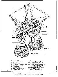 Fig. 13
The Stage I engine assembly was designated LR87-AJ-5. Figure 13 shows the major components of this engine assembly. The engine included two regeneratively cooled thrust chambers, two pump drive assemblies, and interconnecting lines and fittings, all supported by an engine frame. The rocket engine was supplied with propellants from tanks, which were integral with the airframe. The tank bottoms contained outlets and outlet baffles designed to reduce the effects of propellant sloshing and vortexing.
The Stage I oxidizer feed system was a single duct connecting the tank outlet to the oxidizer manifold on the engine. The oxidizer duct was routed through the fuel tank, and was inclosed in a conduit that was a part of the fuel tank. The fuel feed system consisted of two tank outlets to engine interface connectors. The "Stage I engine shutdown" signal was initiated by a thrust chamber pressure switch that sensed a drop in thrust chamber pressure. Staging of the missile was completed when the thrust chamber pressure switch closes and energized the Stage I engine shutdown and staging switch.
The engine frame was made of steel and can withstand 500,000 pounds of thrust. Some of the components and the LR87AJ-5 rocket engine assembly were mounted on the frame. This frame transmited thrust to the missile structure. The frame attached at four points on the missile skirt to the longeron fittings, and at one point on the fuel tank cone. Stage I thrust output was 430,000 pounds at sea level.
Two identical turbopumps delivered the propellants to the thrust chambers at the required flow rates and pressures. Each turbopump assembly consisted of a fuel and oxidizer pump, a gearbox, and two balanced turbine wheels. The fuel and oxidizer pumps were essentially of the same design. The impeller was a single-stage-mixed-flow design with an inducer section and a main head generating section. The inducer section directed the fluid into the main head generating section and compresses the cavitation bubbles formed when the fluid enters. This raised the level of pressure to the main head generating section and prevented the pump from cavitating. The pumps rotated opposite to each other to decrease the gyroscopic effect on the engine frame. The propellants were discharged from the impeller into a volute (a spiral) or collector channel, then through a diffuser nozzle to the discharge piping.
The gearbox acted as a speed reducer between the turbine and the pumps. The turbine speed was 23,000 rpm; the fuel pump turned at 8,850 rpm; and the oxidizer pump at 8,000 rpm. In addition, a 25-horsepower hydraulic pump was driven at 3,800 rpm by the accessory gear train of subassembly 2. The gear train lubrication system contained a five-element lube pump mounted on the accessory pad. The lubrication system also contained a reservoir, heat exchanger, filter, and oil jets. The five-element pump contains four scavenging pumps and one pressure pump. It supplied oil under pressure to the jet, which directed the oil onto the gear train. The oil was directed toward the outgoing side of the gear meshes and toward the inner races of the bearings. The system had baffles, stingers, and channels to properly direct the return flow. The heat exchanger used fuel as the coolant to cool the lube oil. The oil reservoir had a capacity of 7.5 to 8 pounds of lube oil. The turbine assembly was made up of two stages. Each stage contained a nozzle diaphragm that directs the exhaust gases from the gas generator onto the rotor, which drove the turbopump assembly.
The purpose of the thrust chamber was to provide thrust and give directional control. The thrust to propel the missile was developed within the thrust chambers from the combustion of nitrogen tetroxide (N2O4) and Aerozine 50. The thrust chambers were constructed of stainless steel tubing arranged lengthwise. Fuel circulated through the tubing to cool the thrust chambers during operation and to raise the temperature of the fuel to near its flashpoint before it entered the injector.
Valves. The flow of propellants into each thrust chamber was controlled by fuel and oxidizer thrust chamber valves. Locate these valves in figure 13. Both valves were opened at the same time and were controlled by a pressure sequencing valve attached to the thrust chamber valve actuator. During engine start, the thrust chamber valves were opened by the pressure sequencing valve and thrust chamber valve actuator as a result of increasing fuel discharge pressure.
The thrust chambers were mounted on gimbals to permit thrust chamber deflection of 5 degrees in any direction from a neutral position. Propellant transfer lines to the thrust chambers had three flex joints to permit this movement. Their axes of rotation coincided with those of the gimbals. This allowed free thrust chamber assembly movement with fixed turbine pump assemblies. The thrust chambers were adjusted so that their thrust vectors converged 2' toward the centerline of the missile. Converging the thrust vectors in this way steadies the missile during flight.
The gas generator produced hot gas to drive the turbopump assembly (TPA). For starting, a starter cartridge supplied 2000 psia of pressure to the TPA turbine, which turned the TPA. The TPA supplied propellants to the gas generator combustion chamber. The hypergolic propellants ignited and the gas generator exhaust gases drove the TPA to sustain operation.
The starter cartridge, shown in figure 13, supplied high-pressure gases to start the TPA turbine, which turned the propellant pump until the gas generator took over. The cartridge was a solid propellant and burned approximately 1 second, producing approximately 2000 psia to the TPA turbines.
The superheater was a heat exchanger located in the exhaust outlet of the gas generator on subassembly 2. It consisted of coils of stainless tubing that were exposed to the heat of the turbine exhaust. Its function was to convert liquid oxidizer into a gas for the pressurization of the Stage I oxidizer tank.
The propellant tanks were loaded by gravity feed after the missile had been installed in the silo. Both before and during loading, a 6-psig nitrogen blanket was maintained on all tanks. After the tanks had been loaded, a 9- to 14-psig nitrogen pressure was applied to both tanks from a connection on the silo wall to the tank vents. A pressure switch was mounted on top of each tank to monitor this pressure. After the tanks had been pressurized, the nitrogen line was disconnected and the vent is capped.
During flight, pressure was maintained by the engine autogenous pressurization system. The autogenous system generated pressure by extracting hot gas from the turbine housing of the turbine pump assembly. The hot gas was directed through a gas cooler (fig. 13) to cool the gas before it went to the fuel tank for pressurization. The oxidizer tank was pressurized by extracting oxidizer from the TPA, and routing the liquid oxidizer through a super heater where it was changed to a gas for the pressurization of the oxidizer tank.
Stage II Propulsion System.
 Fig. 14
The Stage II propulsion system used a LR91-AJ-5 liquid rocket engine, which was referred to as the "sustainer" engine. Figure 14 identifies the major assemblies of the sustainer engine. The rocket engine assembly was composed of a regeneratively cooled thrust chamber, a turbopump assembly, a starter cartridge, and an electrical sequencer unit. It was supported by a frame assembly. The Stage II engine does not have a superheater.
The operations of Stage II Turbo Pump Assembly were the same as Stage I with the following exceptions. The exhaust from the gas generator was ducted to a roll control nozzle to control roll during sustainer engine operation. The lube pump was a three-element pump and includes one pressure and two scavenger pumps. The oil reservoir had a capacity of 4.5 to 5 pounds of lube oil.
The single thrust chamber of the sustainer engine was smaller, used less propellants, and delivered less thrust than Stage I. The only other difference was the addition of an ablative skirt. The ablative skirt reduces weight and was necessary for a dry jacket start.
The thrust chamber was mounted on a gimbal to permit thrust chamber deflection of 4 degrees in any direction from a neutral position. The Stage II thrust chamber corrected only for pitch and yaw. The roll control nozzle corrected for roll.
Valves, gas generator, and starter cartridge. These three units operated the same as those on Stage I.
There were two solid propellant vernier engines in the Stage II engine compartment. When the sustainer esgine was cut off, the vernier rockets were started by an initiator, as shown in figure 15A. Each engine delivered approximately 1050 pounds of thrust. These engines were used to make final small corrections in velocity and attitude before R/V separation. Their thrust was terminated by a signal from the guidance set. This signal fired gas pressure cartridges, which held the vernier nozzles onto the engines. Termination of vernier thrust ended the powered flight of the missile. The R/V was separated by another guidance signal and then the accessory rockets prevented Stage II from following the R/V on its freefall trajectory.
After the R/V was separated from Stage II, the accessory rockets were sequentially fired to orient Stage II and push it toward the earth.
Shortly after R/V separation, a signal from the guidance set fired the pitch rocket. This rocket was mounted in a cannister inside the Stage II oxidizer tank aft skirt. The rocket was 13 inches long and 5 inches in diameter, It was rated at approximately 530 pounds of thrust at altitude and would burn for approximately 3 seconds, then the depitch rocket fired.
The pitch and depitch rockets were identical in size and thrust. The depitch rocket was mounted 180 degrees away from the pitch rocket. It was fired by a guidance signal shortly after the pitch rocket fired. As soon as the depitch rocket performed its function, the translation rockets were fired.
The two translation rockets were mounted on the outside of the sustainer engine compartment. After the pitch and depitch had oriented Stage II, guidance fired the translation rockets. These rockets produced approximately 5000 pounds of thrust each, for a maximum of 3 seconds.
The sequence of the propulsion system coverage in this section follows the sequence of inflight operation of the various engines. The operational sequence actually starts before launch.
Stage I Engine Operation
The Stage I engine was commonly called the booster engine. Its operation began approximately 30 seconds before launch.
About 30 seconds before rocket engine ignition, the missile's prevalves opened and propellants flowed through the supply lines to the rocket engine turbopump. The rocket engine was started by a 28-volt de power source supplied to the starter cartridge through the engine electrical control system. The starter cartridge propellants ignited, producing hot gases that were directed under high pressure through an inlet nozzle to the turbopump turbine. The force of these hot gases accelerated the turbine very rapidly. The turbine, through a gear train, drove the fuel and oxidizer pumps, which delivered the propellants through the discharge lines to the thrust chamber valves. When pressure within the fuel discharge line reached 295 to 325 psig, the pressure sequencing valve shuttled to the OPEN position, diverting the fuel pressure to the opening side of the fuel butterfly valve actuator. The actuator opened the fuel butterfly valve gate, and the oxidizer butterfly valve was simultaneously opened by mechanical linkage.
When the oxidizer valve opened, oxidizer flowed under pressure into the injector. When the fuel butterfly valve opened, fuel flows down under pressure through alternate coolant tubes of the combustion chamber to a transfer ring at the bottom of the chamber, and then back through alternate tubes into the injector. The fuel was then sprayed into the combustion chamber where it ignited on contact with the oxidizer. The expansion of the ignited gases in the combustion chamber and their accelerated passage from the nozzle produced thrust. Back pressure was created in the propellant lines from pressure developed in the combustion chamber to force small amounts of fuel and oxidizer into the gas generator through the gas generator propellant supply hose assemblies and check valves. A cavitating venturi nipple on each supply hose assembly controlled the flow of propellants.
The check valves were designed to open under a pressure differential of approximately 45 psi to permit propellants to flow through the gas generator injector. Upon contact with each other in the gas generator, the propellants ignited and produced a fuel-rich exhaust gas. This exhaust gas was directed to the turbopump turbine to sustain turbopump operations. The oil pump delivered lubricating oil from the lubricating oil sump to passages within the gearbox assembly as the turbine accelerated. At the same time, oil was directed through jets toward the disengaging side of the gear mesh, against bearing surfaces, and against the carbon seals to cool the seals. Oil was recovered from the gearbox assembly and pumped through the oil cooler and filter screen into the oil sump. Pressure within the gearbox and oil sump was equalized by an interconnecting tube coupled between the gearbox and oil sump. The lubricating oil was cooled by fuel routed from the fuel pump discharge flange, through the core assembly of the oil cooler, and then returned to the fuel pump inlet. Hot gas was bled off from the exhaust pipe and from the fluid heater and directed into the lubricating oil sump for pressurization of the gearbox.
With both the thrust chamber and the gas generator assemblies operating, the rocket engine operated in a steadystate condition. The turbopump operated with the gas generator assembly to supply a constant flow of propellants to the thrust chamber to develop the main engine thrust. The thrust chamber valves were held open by the fuel pump discharge pressure supplied to the fuel valve actuator. The cavitating venturi nipples in the gas generator assembly propellant supply lines maintained a constant flow of fuel and oxidizer to the gas generator assembly over a wide range of propellant discharge pressure variations. This flow tends to provide constant gas generator assembly output and consequently to stabilize turbine speed and constant propellant-pump discharge pressure. This stability of turbine speed and pump pressures resulted in a steady thrust level in the thrust chamber. When approximately 77 percent of rated thrust was obtained, the thrust chamber pressure switch transmits a signal to enable launch.
Stage I engine shutdown was originated by either oxidizer or fuel depletion. The resulting decay in thrust chamber pressure was sensed by the thrust chamber pressure switch, which opened. This caused a 28-volt dc signal to be sent to the override solenoid of the pressure sequencing valve, which caused the main spool in the pressure sequencing valve to close. Fuel discharge pressure was then diverted to the closing side of the fuel butterfly valve actuator to close the thrust chamber valves and terminate engine operation. At the same instant, the pressure switch sends a signal to initiate Stage I separation and Stage II engine start.
Stage II Engine Operation
The sustainer engine operation was basically the same as the booster. The primary difference was in the start and stop functions. When the booster engine thrust decayed, the thrust chamber pressure switch issued a signal to shut down the booster engine and start the sustainer.
As in Stage I, propellants were present in the lines down to the thrust chamber valves. The signal from the thrust chamber pressure switch ignited a solid propellant start cartridge, which generated gases to turn the turbopump. As the turbopump turned, fuel discharge pressure rises causing the thrust chamber valve sequencing valve to shuttle. This opened the thrust chamber valves. As propellants flow to the thrust chamber, some are diverted to the gas generator. As propellants reach the gas generator, they ignite and bootstrap operation begins.
Hot gases from the gas generator were routed through the roll control nozzle. The roll control nozzle directed the hot gases overboard to control roll during Stage II operation. The nozzle could be swiveled in the proper direction to compensate for missile roll deviations. A hydraulic actuator swiveled the nozzle in response to flight control commands. The roll control nozzle generated a minimum thrust of 470 pounds. Before 210 seconds, a guidance signal overrode the thrust chamber pressure sequencing valve, closing the thrust chamber valves and ending sustainer engine operation. At this point in the flight, only minute changes in velocity and attitude were required. The vemiers provided the thrust for these changes.
Vernier engine operation could last for about 20 seconds. At sustainer shutdown, the guidance set sent a signal to ignite the verniers. They operated only until the guidance system verified final trajectory corrections and terminal velocity-then guidance generated a shutdown signal. Vernier thrust buildup required 0.2 second and complete thrust decay occurs within 0.5 second.
When vernier thrust ended, powered flight was over. The R/V was then separated and the accessory rockets began their work.
After R/V separation, the guidance set generated a signal to fire the pitch rockets. The pitch rockets back Stage II away from the R/V and moved it to a nearly vertical position relative to the earth. This movement was stopped by thrust from the depitch rockets, which were also fired by a guidance signal. The translation rockets were then fired to send Stage II toward the ground. The translation rockets thrust was terminated by jettisoning them in response to the final guidance discrete signal.
To insure continuous operation of the liquid propellant rocket engines, the propellants must be provided at a steady continuous rate. The missile tank pressurization systems helped maintain this steady rate of flow.
Pressurization Systems
Both missile stages had autogenous pressurization systems. The Stage I system maintained pressurization of both tanks during flight. The Stage II system maintained only the fuel tank pressure. Both systems were similar, as you will see in the following paragraphs.
Stage I Autogenous Pressurization System.
The Stage I autogenous pressurization system maintained pressure on the Stage I propellant tanks during flight. The major components of the Stage I system were the plumbing and lines to carry the propellants, turbine and gas generator exhaust, and vapors. These lines were made of aluminum alloy with flex lines at strategic points to compensate for vibration and expansion. The cavitating venturi prevented propulsion system runaway by regulating fluid flow at certain locations within the system. As fluid passed through the venturi throat, turbulence was created at the outlet side, which restricted the fluid flow. As the input flow increased, output was reduced because of the turbulence.
The autogenous heat exchanger subassembly cooled hot gases to a more usable temperature by close proximity to a cooling agent. The superheater subassembly vaporizes and disassociates fluids by close proximity to a heating agent. The gas generator used a combustion chamber that provided high-pressure hot gas to operate a turbine, pressurize the fuel tank, and vaporize the oxidizer for pressurizing the oxidizer tank.
Stage I Autogenous Operation
During the launch countdown, the fuel and oxidizer storage valves were opened, allowing the propellants to flow through the inoperative turbines to the thrust chamber valves. At the signal to fire engines, the starter cartridge fires, initiating the rotation of the turbines. This increased the pressure on the propellants, and the thrust chamber valves opened. With the thrust chamber valves open, fuel and oxidizer entered the thrust chamber and the gas generator, and combustion begins. With the gas generator operating: (1) hot gas was furnished to the turbine to maintain rotation and pumping, (2) hot gas was sent to the autogenous heat exchanger for pressurization of the fuel tank, and (3) hot gas was sent to the superheater to vaporize the oxidizer for pressurization of the oxidizer tank. This action continued until the thrust chamber valves were closed at Stage I engine shutdown.
Stage II Autogenous Pressurization System.
In Stage II, the fuel tank was pressurized by the autogenous system. The oxidizer tank required initial nitrogen pressurization only. The system is similar to Stage I, except that the oxidizer pressurization equipment was deleted. The superheater and its associated lines and components were not required. The exhaust gas from the gas generator was routed to a roll control nozzle because the Stage II engine had only one thrust chamber. The operation of the Stage II fuel pressurization system was identical to Stage I fuel pressurization.
The thrust developed by the propulsion system was of little use unless it can be controlled and directed. The hydraulic system provided directional control of this thrust.
Hydraulic Systems
The airborne hydraulic system provides the power to gimbal the thrust chambers and nozzles for missile attitude control. The missile airborne hydraulic system actually consists of two separate systems-one for Stage I and one for Stage II. Operational ground equipment (OGE), at the launch site and MAMS, checks out the missile airborne hydraulic systems.
Please ask permission to use content including pictures and graphics.
© 2007, Copyright by Donald Boelling


 Fig. 12
 W53 Nuclear Warhead
 Fig. 13
 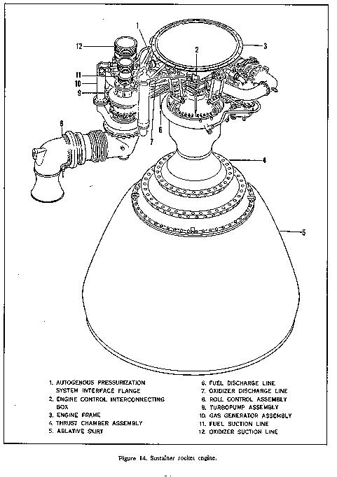 Fig. 14