Missile Launch Complex
In this section we will discuss briefly the surface and below-surface structures that you need to know about.
Above Ground Area
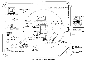 Fig. 1
The following discussion includes both soft and hard structures. Figure 1. includes the surface structures, such as the security fence, lighting system, entry gate, theodolite station, transformer pit, and the access portal. The soft water storage reservoir was a 100,000-gallon tank and was used to replenish the hardened water tank. The propellant transfer system receptacle pit, fuel hardstand, and oxidizer hardstand were used for the emplacement of propellant transfer equipment. The cooling tower pit, complex air, and exhaust duct top structures were part of the cooling and ventilating system. The missile cradle supports, missile crane pad, and missile tiedown were used in missile installation and removal. The antennas, weather instruments, silo door, and access portal door were soft structures. Underground structures include the launch silo, control center, cableway tunnel, blast locks and access portal, diesel fuel tank, fuel dump tank, and oxidizer dump tank.
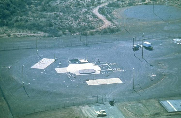 Topside view from the air
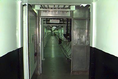
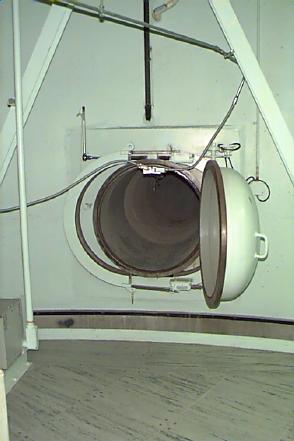
The Access Portal
 Access Portal Entrance
The access portal, shown in the lower left of figure 1, was the normal entrance and exit to the launch control center and launch silo. It was a rectangular concrete structure, about 16 feet square and 34 feet deep, with the top slightly above grade level. The portal contained a stairwell for access to the blast lock and cableway junction. A television camera was mounted between solenoid-operated wire mesh doors in the stairwell. A television monitor in the launch control center enabled the missile combat crew commander (MCCC) to identify incoming personnel. (See fig. 2 for location of most areas discussed in the following paragraphs.)
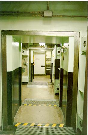
The Blast Lock Area
 Blast Lock Area (Blast doors open)
The blast lock area (fig. 1) was a square, concrete-reinforced area directly attached to the access portal and cableway junction. The blast lock built into the cableway allows access for personnel and equipment to the control center and launch silo without compromising the hard capabilities of the complex. The blast lock was provided with four steel blast doors to protect the control center personnel from an explosion in the launch silo or on the surface. Interlocks for each pair of blast doors prevented the opening of one door before the closing of the other. The blast lock area also served as the rejuvenation and decontamination area for personnel. The blast lock structure provided blast-protected entry from the access portal to the hardened facility, to and from the control center and the launch silo.
The Cableway
 Long Cableway to Launch Silo
The cableway was a concrete structure with steel floors. It extended from the blast lock area to the control center and from the decontamination area to the silo. It provided for passage of personnel and equipment, cables, utility distribution air ducts, and piping. A blast door was installed where the cableway from the control center connects with the blast block area. This blast door separated the blast lock from the decontamination area. A personnel decontamination area, located between the blast lock and silo cableway, contained a dressing room and a decontamination shower. The cableway had a metal floor that could pose certain safety hazards. The floor had to be kept free of oil and hydraulic fluid to prevent injury to personnel through slipping and falling. The electrical cables that lined the sides of the cableway had to be inspected for corrosion and for cracking and deterioration of insulation. Special attention had to be given to the cable connectors to see that they were kept clean and dry at all times.
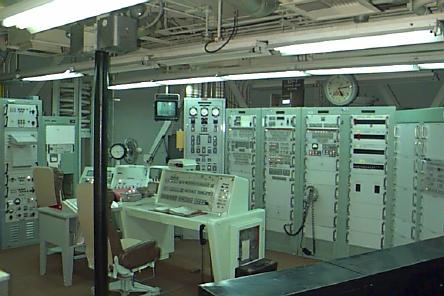
The Control Center
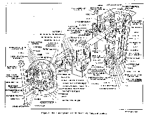 Fig.2
Fig.2
The control center (fig. 2) was a buried, reinforced, concrete structure designed to withstand the effects of a nuclear blast. The ground shock accompanying the blast was nullified in the control center by a three level shock isolation cage supported by eight shock mounts hung form the domed roof. Each shock mount consisted of suspension rods and coil springs. The coil springs were mounted so that they would compress when supporting the static loads. Vertical shock was attenuated by additional compression of the springs. Vertical damping of the system was provided by four rotary-type shock absorbers. The frictional forces in the universal joints of the suspension rods were sufficient to provide damping of the lateral motion.
 Control Center Level 2
The control center was a three-level structure with a 1-foot "rattle space" between the outer walls and each level of the control center structure. The three levels of the control center were connected by steel stairways. Level 1 had sleeping quarters, a vestibule, a kitchen and dining area, a mechanical equipment room, and a latrine. Level 2 was connected to the cableway and personnel tunnel and also to the air intake shaft. This level had the controls for launching the missile and for monitoring the operations of the entire complex.
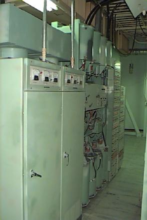 Control Center Level 3 Communication Racks
Control center level 3 contained the cable vault, sewage lift station, communications, electrical power equipment, and escape hatch assembly (emergency exit).
 Control Center Level 3 Escape Hatch (Open)
The escape hatch opened into the air intake shaft, which had a steel-runged ladder that ran from the top to the bottom. The air intake shaft was approximately 46 feet long and 3 feet in diameter.
The Missile Silo
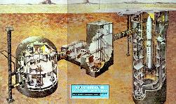 Complex Layout, Click to download. (325K est. 5 minutes at 28.8 bps)
The missile silo was a reinforced concrete structure with inside dimensions of approximately 146 feet in depth and 55 feet in diameter. A launch duct, with an acoustical lining, was located in the center of the silo. Associated installed equipment, structures, and mechanisms included a survey transfer station, silo closure door, retractable work platforms, a collimator room, hazard sensing devices, and a small equipment and personnel elevator operating between levels 2 and 8. Two exhaust ducts carried missile exhaust and ingested air from the flame deflector, through cascade vanes, to the surface. Equipment areas were located between the launch duct and the missile silo walls on nine separate levels. Equipment contained on the various levels is described in the following paragraphs.
The silo closure door. This door was a steel and concrete structure designed to protect the silo from nearby nuclear blasts and resulting radiation. When closed, the door rested upon a seal with wheel trucks clear of the rails. Door locks held the door in position, preventing movement from shock or vibration. The silo closure door system consisted of the closure door, wheel trucks, track rails, buffers, and a door-actuating system. The actuating system consisted of rail bridge jacks, door locks, a drive unit, cables, a pneudraulic power system, and electrical, hydraulic, and pneumatic controls.
The door normally opened automatically during launch sequence by the control-monitor group in the control center. The drive unit opened the closure door within 17 to 21 seconds, including unlocking and raising time. For maintenance, the door could be opened or closed locally from the silo closure maintenance control panel located at silo level 1. Refer to figure 2 for identification and location of equipment in the launch silo work areas.
Silo level 1
There were two groups of equipment located on silo level 1. The elevator power control equipment operated the silo personnel and equipment elevator. The other group of equipment was used to open and close the silo door. Silo retractable work platforms were located on this level to allow access to the missile re-entry vehicle.
Silo level 2
The collimator room, which housed the missile guidance system alignment equipment, was located on level 2. This equipment was deactivated and remove in the late 1970’s when the old guidance system was replaced with a modern, state-of-the-art, guidance system. On the opposite side of the silo at level 2, all the equipment for the chilled water system was mounted on a shock isolation platform. Silo retractable work platforms and the cableway tunnel were located at this silo level. Also the missile air conditioner, and an emergency eyewash and shower were located on this level.
Silo level 3
Level 3 housed the diesel generator engine, motor control center and switch gear, steam separator, outside air intake and exhaust vent, filter, supply and exhaust fan, emergency shower, and the manhole for access to the hard water tank. The diesel generator supplied power to the site in the event commercial power was interrupted. The diesel generator was a six-cylinder, supercharged, 510 brake horsepower @ 900 RPM, engine similar to that used in diesel locomotives. Access to two retractable work platforms was also at this level.
Silo level 4
This silo level contains a supply and an exhaust fan, outside air intake and exhaust vents, and the equipment area air conditioner.
Silo level 5
The launch duct air conditioner, slop tank for fuel and lube oil, diesel service tank, and part of the water tank were on this level. There was also a retractable work platform at this level as well as the personnel and equipment elevator.
Silo level 6
Of particular interest on this level was the vapor detection controls. Because of the characteristics of Titan II propellants, this equipment had to always be operable when the missile was fueled or in the process of being fueled. The safety of work crews and launch crew depended on the proper operation of this equipment.
Silo level 7
This level provided access to the thrust mount. The thrust mount was a large ring suspended from the silo walls by shock isolation springs and dampers. The Titan missile rested on the thrust mount and was bolted in place with explosive bolts which blew apart during the launch sequence to release the missile.
Silo levels 8 and 9
Both the fuel and oxidizer pump rooms were located on level 8, and that adjacent to each was an emergency eyewash and shower. Access to level 9 was through hatches and down ladders. The engine's exhaust flames were deflected into the exhaust duct and then up through the exhaust duct deflection vanes.
Please ask permission to use content including pictures and graphics.
© 2007, Copyright by Donald Boelling


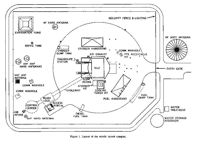 Fig. 1
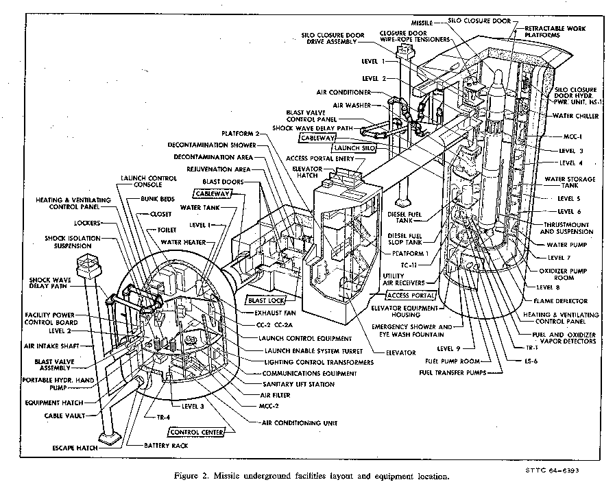 Fig.2
Fig.2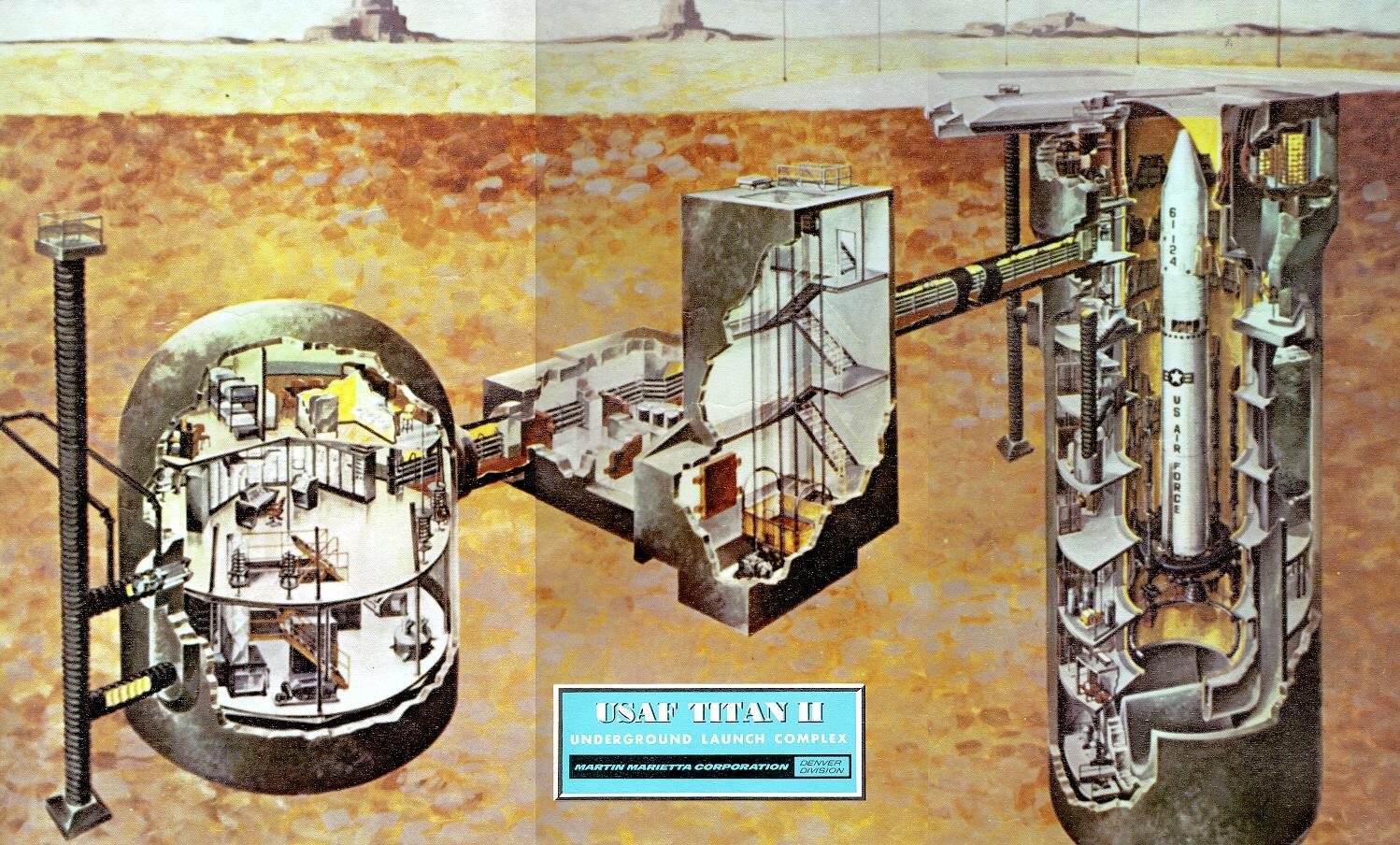 Complex Layout, Click to download. (325K est. 5 minutes at 28.8 bps)